In this webinar recording we discuss the processes involved with leveraging the full potential of the Building Information Model for layout purposes. We also outlined process for exporting an IFC model from the design authoring software.
Archive for Training & Maintenance Videos
Test description
Webinar discussing data creation inside Trimble Field Link. Showing file opening and file importing sequences as well as creating data and points on the fly . Examples given for creating points using a drawing, a model or creating data without a drawing.
IN this video we review the steps necessary to establish a connection between the tablet and the RPT600. Please note that the RPT600 is our WiFi only connection. This connection is different than the connection to any of our RTS Series guns and their 2.4GHz Radio.
IN this video we demonstrate some techniques for setting up a tripod, placing a Robotic Total Station on that tripod and leveling the instrument. This demonstration is suitable if you use a robotic total station, a manual total station of a transit. We also point out the reason why we prefer the use of our fiberglass TriMax tripods to the use of others.
In this video we walk you through the process of using the onboard digital level in a Trimble Robotic Total Station. This is our preferred method of leveling your instrument and we walk you through the steps and how to adjust the accuracy of the onboard digital level.
Our Trimble Robotic Total Stations allow users to use both a viable and invisible laser to perform layout tasks and collect data. IN this video we introduce the basics of how those two modes work and how the user can change the settings to perform layout and collection tasks using the laser or the more traditional prism and pole to measure.
The best way to setup and use your Robotic Total Station is to set it up in a good location and then have clear line of sight to perform your layout tasks. Here we cover one of the first steps in completing layout tasks and that is establishing the instrument location on the building site using control points and shooting a resection of the layout area.
Trimble Field Link offers users the ability to create data. This can be creating points to layout on an existing drawing or model. Please note that you can load the following drawing types into Trimble Field Link: DWG, DXF, IFC, SKP, PDF.
We also demonstrate how you can create a DWG export by creating line work connecting collected points.
We then demonstrate how to create Grids and Patterns of points to expedite you ability to create layout points in your file.
Trimble Field Link offers the ability of the users to generate multiple reports. These reports can show productivity, accuracy as well as document conditions encountered on the job site along with photographs. This video describes the process of generating these reports.
Trimble Field Link software not only offers the ability to import data to aid in creating layout data for projects but you can also export data as well. Creating data that is rich in spatial information can aid in creating better defined models and dramatically aids the speed and accuracy of modeling for prefabrication. This video shows users how to leverage these capabilities.
Trimble Field Link is a diverse software that allows you to utilize one software platform to operate multiple Trimble devices for layout and collection of field data. TFL software connects to the RPT Series, RTS Series, SPS Series and the X7 Scanner.
In this video we walk users through the interface and options on how to connect to these various devices as well as how to change the RPT and RTS Series from Prism (Invisible Laser) and Laser Layout modes.
Trimble Field Link not only allows you to import and view a variety of files (DWG, DXF, IFC, SKP and PDF) but it also offers you the ability to use the layer control in the drawing files as well. You can also manage the descriptions of your points (names, descriptions, etc.).
In this video we demonstrate where those controls are located and how they work.
Trimble Field Link works with both 2-dimensional drawings and 3-dimensional models. With those two formats being drastically different it required the software to include a variety of Map/Plan view navigation buttons.
In this video we demonstrate where these buttons are located and how they function.
Trimble Field Link allows users to perform all normal duties associated with layout on a construction project but, it also allows users to collect data in the field or locate penetrations in a wall or other vertical surface.
In this video we demonstrate all of the functions performed in the “Measure” menu in detail.
Trimble Field Link has built-in tools to help the user provide additional information from the measured points on a project.
In this video we demonstrate how users can:
– measure the distance and slope between points
– measure the angle between points
– measure an area or volume
– perform the down and out measurements

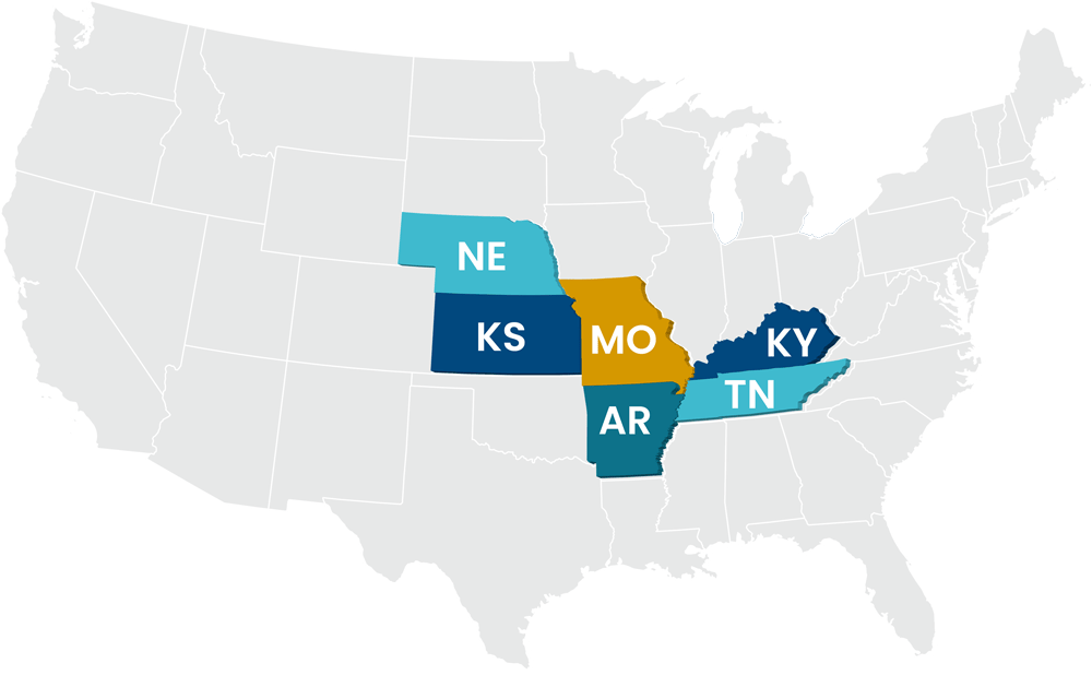
In our sales territory?
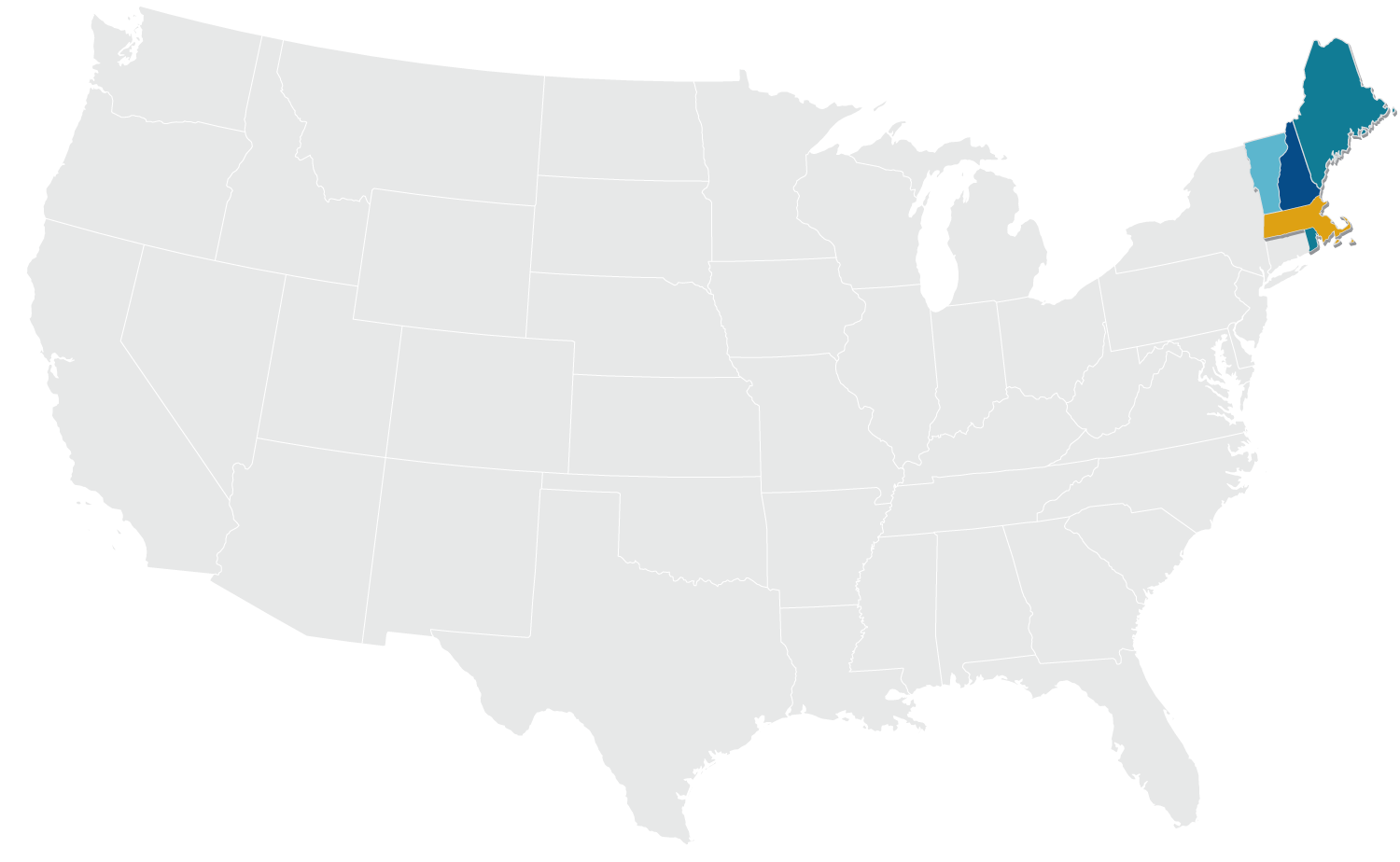
Not in our sales territory?
BuildingPoint Mid-America, LLC – Headquarters
3433 Tree Court Industrial Blvd.
St. Louis, MO 63122
(314)526-2074
Nashville Office
810 Royal Parkway, Suite 110
Nashville, TN 37214
(615)992-6990


